Overview
At work I was given a task to render a polyline with screen space invariant width. This includes following steps:
- Render polyline with simple quads (this post).
- Render polyline with rounded joins (second post).
- Render polyline with different caps on sides (third post).
- Render polyline with different join styles (fourth post).
- Render polyline with dash pattern (fifth post).
Standard way
Implementation
The traditional way is to render lines with GL_LINE_STRIP:
glEnable(GL_LINE_SMOOTH);
glEnable(GL_BLEND);
glDepthMask(false);
glLineWidth(lw);
glDrawArrays(GL_LINE_STRIP, offset, count);
- Enable line smoothing by calling
glEnable(GL_LINE_SMOOTH). In hardware it works by adjusting pixels’ alpha values. That’s why you have to do the next step. - Enable blending with
glEnable(GL_BLEND); - Disable writing to the depth buffer with
glDepthMask(false). When rendering lines, especially thick ones, one pixel can be drawn several times with different alpha and z values. And sometimes a more dark pixel may appear below a lighter pixel because of the Z fighting. And if theGL_DEPTH_TESTis enabled (usually you want to have it be enabled) the dark pixel won’t be drawn and the final image will have a visible gap in this place. That’s why you have to disable writing to the depth buffer. - Set the line width by calling
glLineWidth(lw). - Draw the lines.
Problems
If you follow these steps, the quality of AA lines at least on NVidia is pretty decent, but there are some problems.
- The quality depends on the hardware implementation. So it might be good on NVidia, bad on Intel, you never know.
- Poor performance on latest NVidia GeForce cards. It might be a marketing trick to make people buy professional Quadro cards, but it is how it is, the time of rendering antialiased lines with NVidia GeForce OpenGL is dramatically longer (50-100 times maybe) than one of the alised lines.
Shader way
The most common approach is to render quads for each line. Nicolas P. Rougier in his article suggested to use two common vertices for join of two quads, that position is calculated in shader. The downside of this approach is when we have angles close to 180 degrees and vertices on join will go to infinity.
Implementation specifics
To avoid problem I mentioned above I decided to render quads and rounding it on joins.
For example, we have have polyline defined by n points:
\[P_1, P_2, ... P_n\]So we will have n-1 segments.
To get the correct vertex position of quad we need point position and offset in texture coordinates. These values we will store in vertex buffer. Also we need a direction of offset.
Direction calculation
To calculate proper vertices offset for quads we need screen space line direction. I invented a trick to calculate direction in shader without additional memory usage.
At first we gonna add two additional segments by extrapolating first and last ones:
\[\begin{cases} P_0 = P_1 + (P_1 - P_2) \\ P_{n+1} = P_n + (P_n - P_{n-1}) \end{cases}\]Vertices layout will be following:
\[\begin{cases} (P_0, P_0, P_1, P_1) \\ (P_1, P_1, P_2, P_2) \\ (P_2, P_2, P_3, P_3) \\ \dotso \\ (P_n, P_n, P_{n+1}, P_{n+1}) \end{cases} \tag{1}\label{1}\]The direction should be the same for all vertices of a single quad. I came up with an idea that if we sum up two vectors: from vertex before current by two vertices to current vertex and from current vertex to vertex after current by two vertices, we get the invariant value across all vertices of quad.
According to memory layout $\eqref{1}$, the direction vectors for i-th quad will be calculated as:
\[\begin{cases} d_0 = (P_{i} - P_{i}) + (P_{i+1} - P_{i}) = P_{i+1} - P_{i} \\ d_1 = (P_{i} - P_{i}) + (P_{i+1} - P_{i}) = P_{i+1} - P_{i} \\ d_2 = (P_{i+1} - P_{i}) + (P_{i+1} - P_{i+1}) = P_{i+1} - P_{i} \\ d_3 = (P_{i+1} - P_{i}) + (P_{i+1} - P_{i+1}) = P_{i+1} - P_{i} \end{cases} \tag{2}\label{2}\]For example, lets assume that we are rendering the first quad:
\[(P_1, P_1, P_2, P_2)\]From equation $\eqref{2}$ direction vectors for this quad will be calculated as:
\[\begin{cases} d_0 = (P_1 - P_1) + (P_2 - P_1) = P_2 - P_1 \\ d_1 = (P_1 - P_1) + (P_2 - P_1) = P_2 - P_1 \\ d_2 = (P_2 - P_1) + (P_2 - P_2) = P_2 - P_1 \\ d_3 = (P_2 - P_1) + (P_2 - P_2) = P_2 - P_1 \end{cases}\]Vertex layout
Vertex layout is following:
struct alignas(4) Vertex
{
    Point3DF position; // vec3
    PointF texcoord;   // vec2
};
Data creation code
Full data creation code is following:
bool PolylineDrawer::CreateData()
{
    // Allocate buffer at first
    uint32_t numPoints = static_cast<uint32_t>(m_points.size());
    VSN_ASSERT(numPoints >= 2);
    uint32_t numSegments = numPoints - 1;
    uint32_t totalSegments = numSegments + 2; // we add two additional segments before and after

    VSN_ASSERT(m_verticesArray == nullptr);
    m_numVertices = 4 * totalSegments;
    m_vertexSize = sizeof(Vertex);
    m_verticesArray = new uint8_t[m_numVertices * m_vertexSize];
    if (m_verticesArray == nullptr)
        return false;

    VSN_ASSERT(m_indicesArray == nullptr);
    m_numIndices = 6 * numSegments;
    m_indexSize = sizeof(uint32_t);
    m_indicesArray = new uint8_t[m_numIndices * m_indexSize];
    if (m_indicesArray == nullptr)
        return false;

    // Fill data
    Vertex* vertices = reinterpret_cast<Vertex*>(m_verticesArray);
    uint32_t* indices = reinterpret_cast<uint32_t*>(m_indicesArray);

    // Positions
    uint32_t n = 0;
    // First segment points (extrapolate starting segment to get first point)
    Point3DF firstPoint = m_points[0] + (m_points[0] - m_points[1]);
    vertices[n++].position = firstPoint;
    vertices[n++].position = firstPoint;
    vertices[n++].position = m_points[0];
    vertices[n++].position = m_points[0];
    for (uint32_t i = 0; i < numSegments; ++i) // enumerate original segments
    {
        const Point3DF& point1 = m_points[i];
        const Point3DF& point2 = m_points[i+1];
        vertices[n++].position = point1;
        vertices[n++].position = point1;
        vertices[n++].position = point2;
        vertices[n++].position = point2;
    }
    // Last segment points
    Point3DF lastPoint = m_points[numPoints-1] + (m_points[numPoints-1] - m_points[numPoints-2]);
    vertices[n++].position = m_points[numPoints-1];
    vertices[n++].position = m_points[numPoints-1];
    vertices[n++].position = lastPoint;
    vertices[n++].position = lastPoint;

    // Texcoords
    n = 0;
    for (uint32_t i = 0; i < totalSegments; ++i)
    {
        vertices[n++].texcoord.Init(-1.0f,  1.0f);
        vertices[n++].texcoord.Init(-1.0f, -1.0f);
        vertices[n++].texcoord.Init( 1.0f,  1.0f);
        vertices[n++].texcoord.Init( 1.0f, -1.0f);
    }

    // Indices
    n = 0;
    for (uint32_t i = 0; i < numSegments; ++i)
    {
        // 0-1-2
        indices[n++] = 4*i+0;
        indices[n++] = 4*i+1;
        indices[n++] = 4*i+2;
        // 2-1-3
        indices[n++] = 4*i+2;
        indices[n++] = 4*i+1;
        indices[n++] = 4*i+3;
    }

    // Free points data
    m_points.resize(0);
    m_points.shrink_to_fit();

    return true;
}
Attributes layout
We need to have two additional attributes for previous points and next points for computation in vertex shader.
The attribute definition code is following:
// Attributes layout
const GLsizei stride = sizeof(Vertex);
const uint8_t* base = nullptr;
const uint8_t* currOffset = base + 4*stride; // offset to start of actual current data
const uint8_t* prevOffset = currOffset - 2*stride;
const uint8_t* nextOffset = currOffset + 2*stride;
const uint8_t* texcoordOffset = currOffset + sizeof(Point3DF);
funcs->glVertexAttribPointer(0, 3, GL_FLOAT, GL_FALSE, stride, prevOffset); // vec3 a_prev
funcs->glEnableVertexAttribArray(0);
funcs->glVertexAttribPointer(1, 3, GL_FLOAT, GL_FALSE, stride, currOffset); // vec3 a_curr
funcs->glEnableVertexAttribArray(1);
funcs->glVertexAttribPointer(2, 3, GL_FLOAT, GL_FALSE, stride, nextOffset); // vec3 a_next
funcs->glEnableVertexAttribArray(2);
funcs->glVertexAttribPointer(3, 2, GL_FLOAT, GL_FALSE, stride, texcoordOffset); // vec2 a_texcoord;
funcs->glEnableVertexAttribArray(3);
Shader code
The direction in shader will have following formula:
\[d = (P_{curr} - P_{prev}) + (P_{next} - P_{curr}) = P_{next} - P_{prev}\]Vertex shader:
#version 330 core

layout(location = 0) in vec3 a_prev;
layout(location = 1) in vec3 a_curr;
layout(location = 2) in vec3 a_next;
layout(location = 3) in vec2 a_texcoord;

uniform mat4 u_proj;
uniform mat4 u_view;
uniform mat4 u_model;
uniform vec4 u_viewport;
uniform float u_width;

vec2 project(vec4 clip)
{
    vec3 ndc = clip.xyz / clip.w;
    vec2 screen = (ndc.xy * 0.5 + vec2(0.5)) * u_viewport.zw + u_viewport.xy;
    return screen;
}
vec4 unproject(vec2 screen, float z, float w)
{
    vec2 ndc = ((screen - u_viewport.xy) / u_viewport.zw - vec2(0.5)) * 2.0;
    return vec4(ndc.x * w, ndc.y * w, z, w);
}

void main()
{
    mat4 mvp = u_proj * u_view * u_model;

    vec4 clip_curr = mvp * vec4(a_curr, 1.0);
    vec4 clip_prev = mvp * vec4(a_prev, 1.0);
    vec4 clip_next = mvp * vec4(a_next, 1.0);

    vec2 curr = project(clip_curr);
    vec2 prev = project(clip_prev);
    vec2 next = project(clip_next);

    vec2 direction = normalize(next - prev);
    vec2 normal = vec2(-direction.y, direction.x);

    float w = u_width * 0.5;
    vec2 offset_x = direction * (a_texcoord.x * w);
    vec2 offset_y = normal    * (a_texcoord.y * w);
    vec2 screen = curr + offset_x + offset_y;

    gl_Position = unproject(screen, clip_curr.z, clip_curr.w);
}
Fragment shader:
#version 330 core

uniform vec4 u_color;

out vec4 color;

void main()
{
    color = u_color;
}
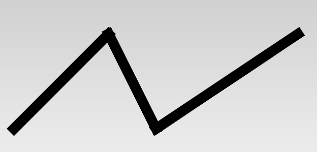
Conclusion

We achieved screen space based base version of polyline rendering. Roundings will be covered in the next post.